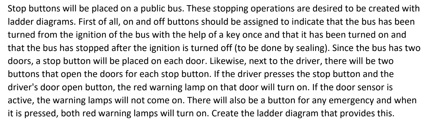
Bus Automation


Stop buttons will be placed on a public bus. These stopping operations are desired to be created with ladder diagrams. First of all, on and off buttons should be assigned to indicate that the bus has been turned from the ignition of the bus with the help of a key once and that it has been turned on and that the bus has stopped after the ignition is turned off (to be done by sealing). Since the bus has two doors, a stop button will be placed on each door. Likewise, next to the driver, there will be two buttons that open the doors for each stop button. If the driver presses the stop button and the driver's door open button, the red warning lamp on that door will turn on. If the door sensor is active, the warning lamps will not come on. There will also be a button for any emergency and when it is pressed, both red warning lamps will turn on. Create the ladder diagram that provides this.

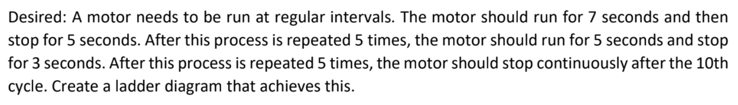
Motor Driver Automation


A motor needs to be run at regular intervals. The motor should run for 7 seconds and then stop for 5 seconds. After this process is repeated 5 times, the motor should run for 5 seconds and stop for 3 seconds. After this process is repeated 5 times, the motor should stop continuously after the 10th cycle. Create a ladder diagram that achieves this.

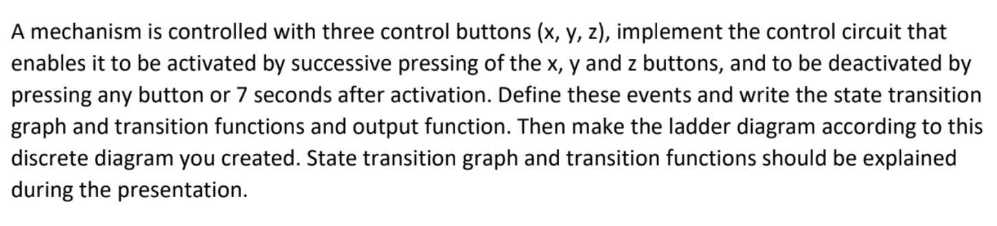
Control Circuit Transition Diagram
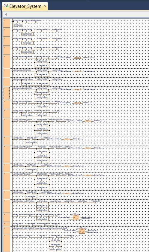

A mechanism is controlled with three control buttons (x, y, z), implement the control circuit that enables it to be activated by successive pressing of the x, y and z buttons, and to be deactivated by pressing any button or 7 seconds after activation. Define these events and write the state transition graph and transition functions and output function. Then make the ladder diagram according to this discrete diagram you created. State transition graph and transition functions should be explained during the presentation.

Elevator Automation


elevator automation ladder diagram

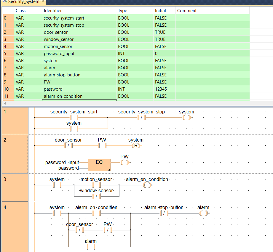
Security System Automation


security system ladder diagram

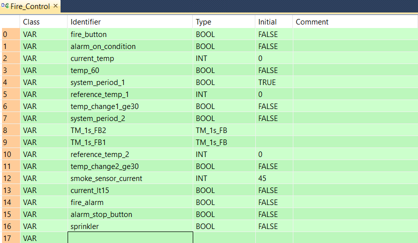
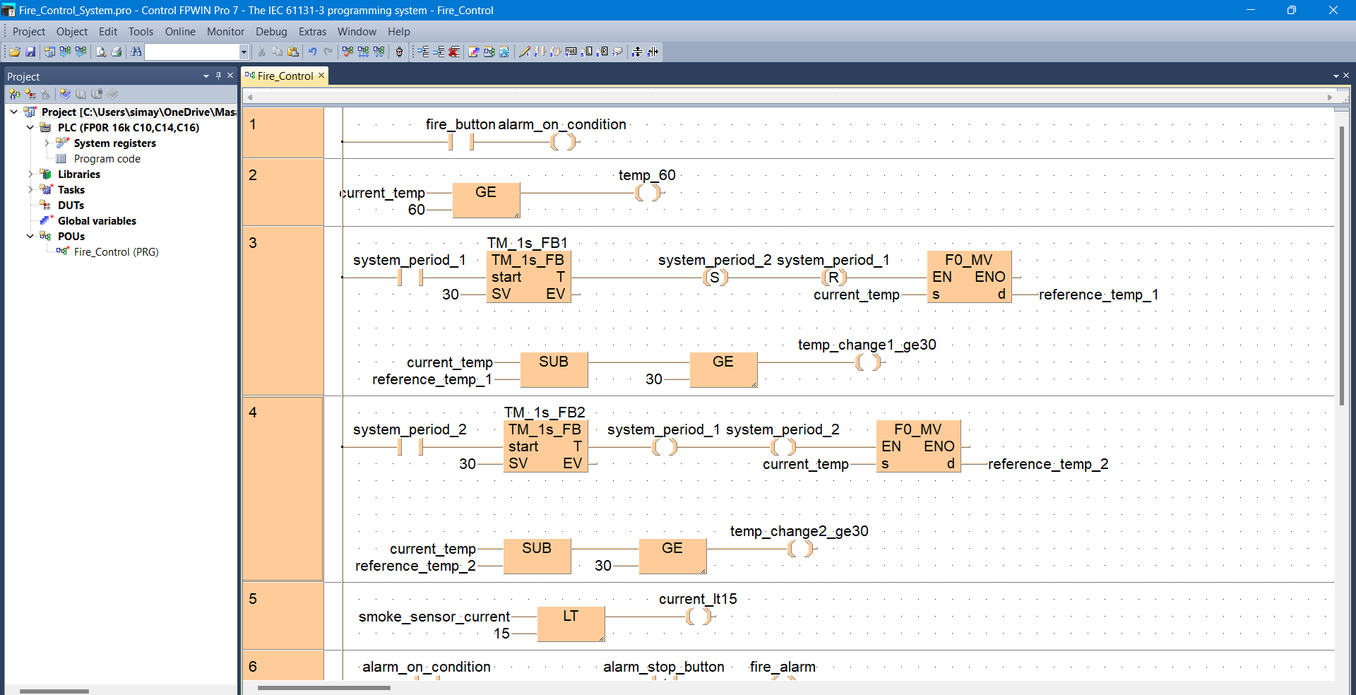
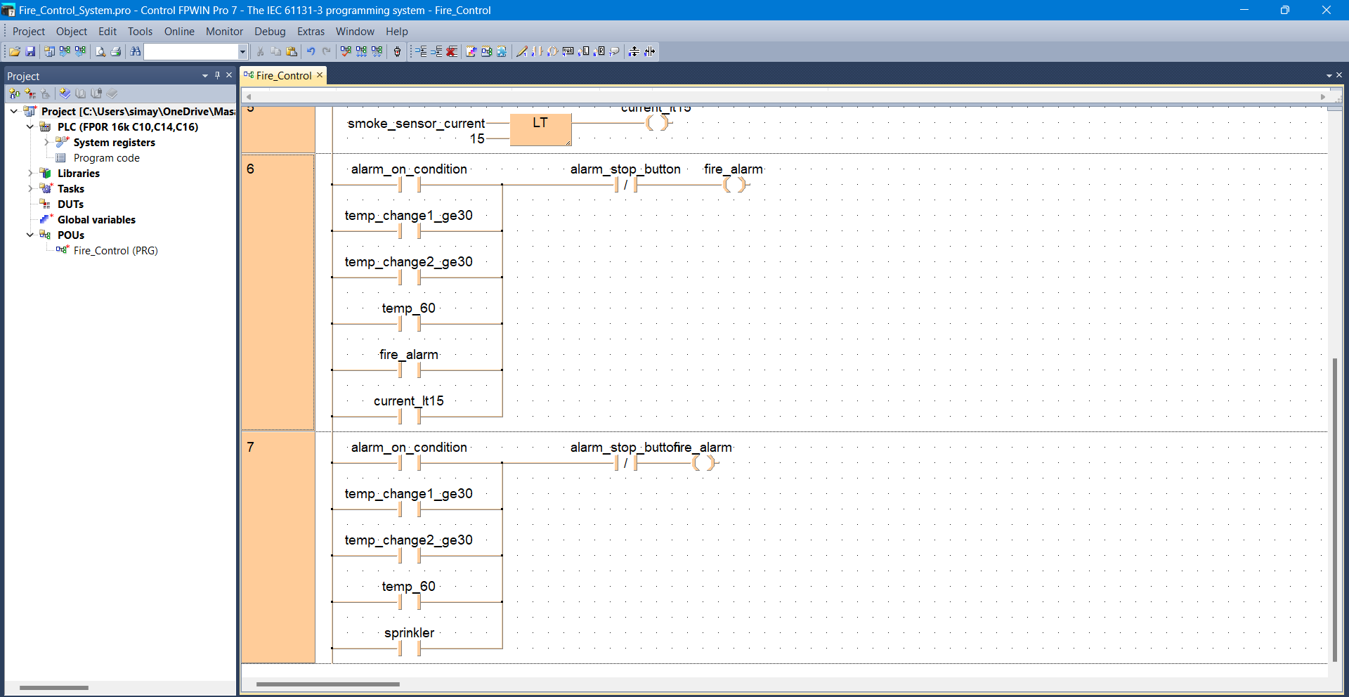
Fire Control System Automation


fire control system ladder diagram fire control system ladder diagram fire control system ladder diagram

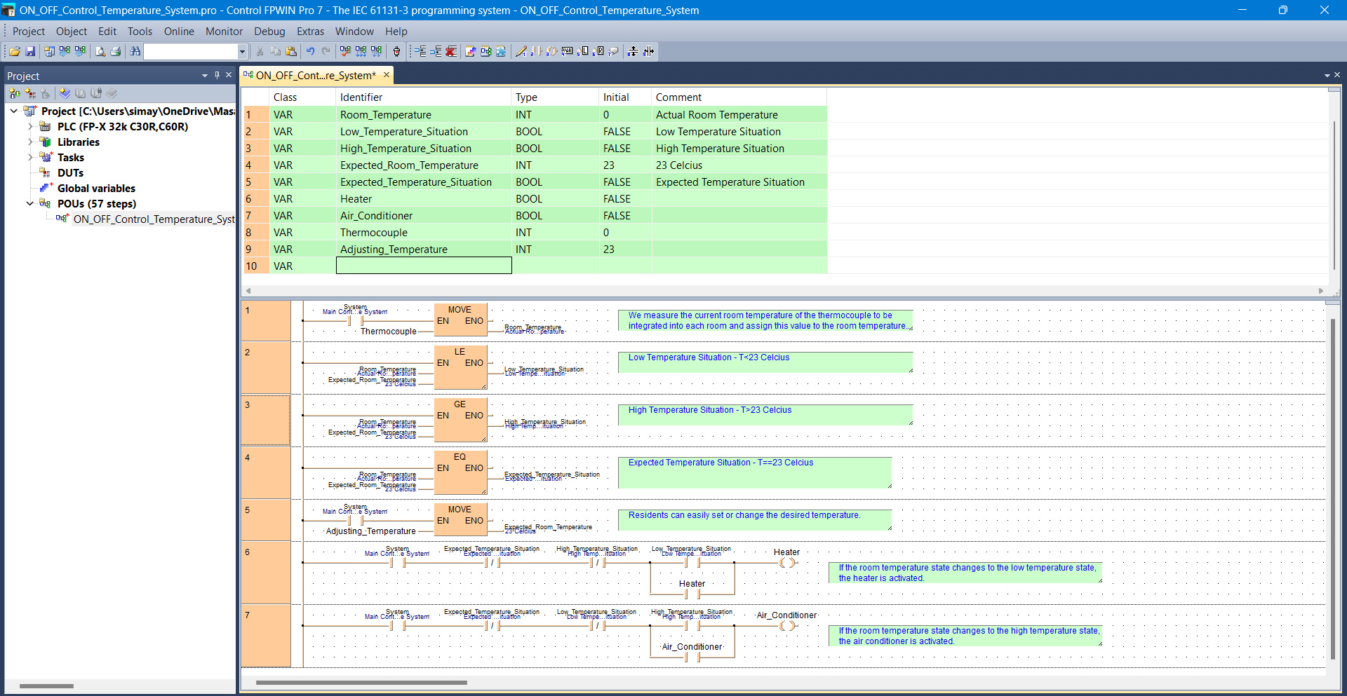
ON/OFF Control Temperature System Automation


ON/OFF Control Temperature System ladder diagram

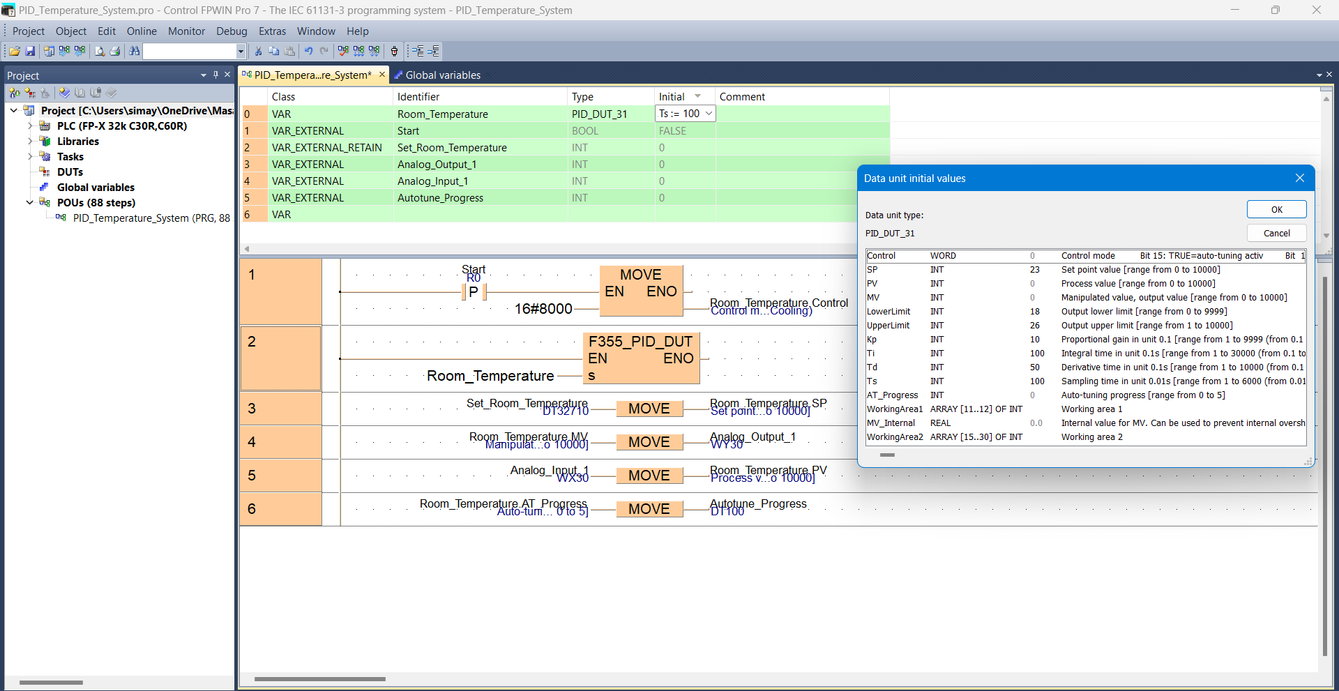
PID Temperature System Automation


PID Temperature System ladder diagram

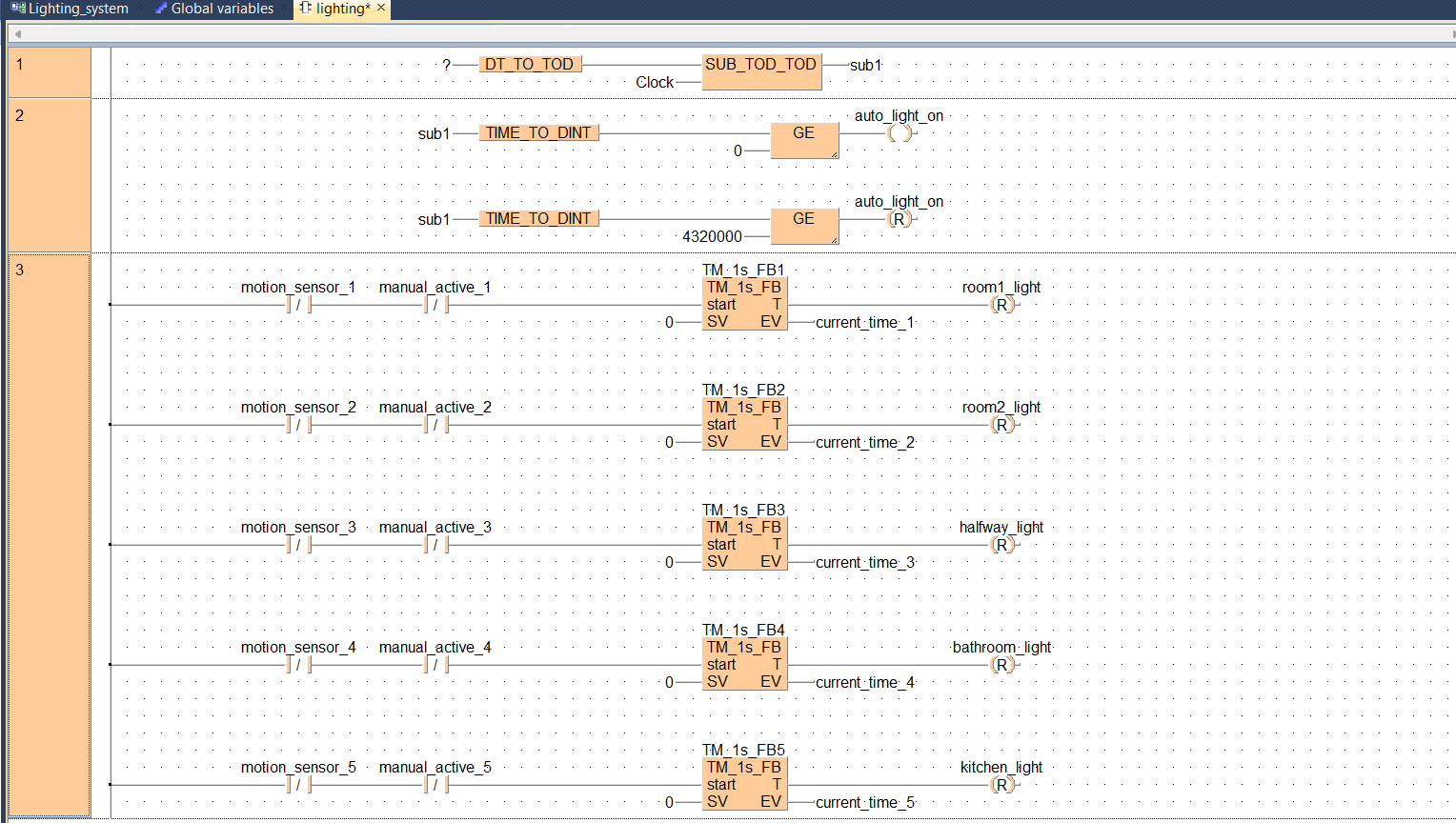
Lighting System Automation


Lighting System ladder diagram

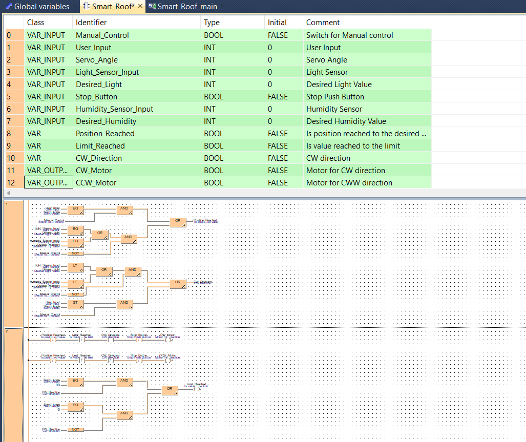
Roof System Automation


Roof System ladder diagram

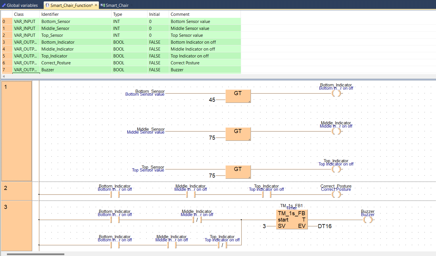
Smart Chair System Automation


Smart Chair System ladder diagram

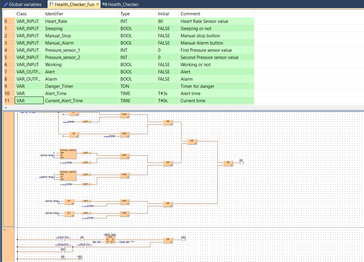
Health Checking System Automation


Health Checking System ladder diagram