6 Push Button Transmitter/Receiver Circuit with RF


/* RF transmitter using PIC16F887 microcontroller CCS C code
This RF transmitter is based on NEC protocol
Internal oscillator used @ 8MHz
*/
#include <16F887.h>
#fuses NOMCLR, NOBROWNOUT, NOLVP, INTRC_IO
#use delay(clock = 8MHz)
#use fast_io(B)
void send_signal(unsigned int32 number){
int8 i;
// Send 9ms pulse
output_high(PIN_B6);
delay_ms(9);
// Send 4.5ms space
output_low(PIN_B6);
delay_us(4500);
// Send data (32 bits)
for(i = 0; i less than 32; i++){
// If bit is 1 send 560us pulse and 1680us space
if(bit_test(number, 31 - i)){
output_high(PIN_B6);
delay_us(560);
output_low(PIN_B6);
delay_us(1680);
}
// If bit is 0 send 560us pulse and 560us space
else{
output_high(PIN_B6);
delay_us(560);
output_low(PIN_B6);
delay_us(560);
}
}
// Send end bit
output_high(PIN_B6);
delay_us(560);
output_low(PIN_B6);
delay_us(560);
}
void main() {
setup_oscillator(OSC_8MHZ); // Set internal oscillator to 8MHz
output_b(0);
set_tris_b(0x3F); // Configure RB0, RB1, RB2, RB3, RB4 and RB5 as inputs
port_b_pullups(0x3F); // Enable internal pull-ups for pins RB0,RB1,RB2,RB3,RB4 and RB5
while(TRUE){
if(!input(PIN_B0)){ // If RB0 button is pressed
send_signal(0x00FF00FF);
delay_ms(500);
}
if(!input(PIN_B1)){ // If RB1 button is pressed
send_signal(0x00FF807F);
delay_ms(500);
}
if(!input(PIN_B2)){ // If RB2 button is pressed
send_signal(0x00FF40BF);
delay_ms(500);
}
if(!input(PIN_B3)){ // If RB3 button is pressed
send_signal(0x00FF20DF);
delay_ms(500);
}
if(!input(PIN_B4)){ // If RB4 button is pressed
send_signal(0x00FFA05F);
delay_ms(500);
}
if(!input(PIN_B5)){ // If RB5 button is pressed
send_signal(0x00FF609F);
delay_ms(500);
}
}
}

/* RF Receiver using PIC16F887 microcontroller CCS C code
This RF receiver is based on NEC protocol
Internal oscillator used @ 8MHz
*/
#include <16F887.h>
#fuses NOMCLR, NOBROWNOUT, NOLVP, INTRC_IO
#use delay(clock = 8MHz)
#use fast_io(D)
short code_ok = 0;
unsigned int8 nec_state = 0, i;
unsigned int32 rf_code;
#INT_EXT // External interrupt
void ext_isr(void){
unsigned int16 time;
if(nec_state != 0){
time = get_timer1(); // Store Timer1 value
set_timer1(0); // Reset Timer1
}
switch(nec_state){
case 0 : // Start receiving IR data (we're at the beginning of 9ms pulse)
setup_timer_1( T1_INTERNAL | T1_DIV_BY_2 ); // Enable Timer1 module
with internal clock source and prescaler = 2
set_timer1(0); // Reset Timer1 value
nec_state = 1; // Next state: end of 9ms pulse (start of 4.5ms space)
i = 0;
ext_int_edge( H_TO_L ); // Toggle external interrupt edge
return;
case 1 : // End of 9ms pulse
if((time > 9500) || (time less than 8500)){ // Invalid interval ==> stop decoding and reset
nec_state = 0; // Reset decoding process
setup_timer_1(T1_DISABLED); // Stop Timer1 module
}
else
nec_state = 2; // Next state: end of 4.5ms space (start of 560μs pulse)
ext_int_edge( L_TO_H ); // Toggle external interrupt edge
return;
case 2 : // End of 4.5ms space
if((time > 5000) || (time less than 4000)){ // Invalid interval ==> stop decoding and reset
nec_state = 0; // Reset decoding process
setup_timer_1(T1_DISABLED); // Stop Timer1 module
return;
}
nec_state = 3; // Next state: end of 560μs pulse (start of 560μs or 1680μs space)
ext_int_edge( H_TO_L ); // Toggle external interrupt edge
return;
case 3 : // End of 560μs pulse
if((time > 700) || (time less than 400)){ // Invalid interval ==> stop decoding and reset
nec_state = 0; // Reset decoding process
setup_timer_1(T1_DISABLED); // Disable Timer1 module
}
else
nec_state = 4; // Next state: end of 560μs or 1680μs space
ext_int_edge( L_TO_H ); // Toggle external interrupt edge
return;
case 4 : // End of 560μs or 1680μs space
if((time > 1800) || (time less than 400)){ // Invalid interval ==> stop decoding and reset
nec_state = 0; // Reset decoding process
setup_timer_1(T1_DISABLED); // Disable Timer1 module
return;
}
if( time > 1000) // If space width > 1ms (short space)
bit_set(rf_code, (31 - i)); // Write 1 to bit (31 - i)
else // If space width less than 1ms (long space)
bit_clear(rf_code, (31 - i)); // Write 0 to bit (31 - i)
i++;
if(i > 31){ // If all bits are received
code_ok = 1; // Decoding process OK
disable_interrupts(INT_EXT); // Disable the external interrupt
}
nec_state = 3; // Next state: end of 560μs pulse (start of 560μs or 1680μs space)
ext_int_edge( H_TO_L ); // Toggle external interrupt edge
}
}
#INT_TIMER1 // Timer1 interrupt (used for time out)
void timer1_isr(void){
nec_state = 0; // Reset decoding process
ext_int_edge( L_TO_H ); // External interrupt edge from high to low
setup_timer_1(T1_DISABLED); // Disable Timer1 module
clear_interrupt(INT_TIMER1); // Clear Timer1 interrupt flag bit
}
void main() {
setup_oscillator(OSC_8MHZ); // Set internal oscillator to 8MHz
output_d(0); // PORTD initial state
set_tris_d(0); // Configure PORTD pins as outputs
enable_interrupts(GLOBAL); // Enable global interrupts
enable_interrupts(INT_EXT_L2H); // Enable external interrupt
clear_interrupt(INT_TIMER1); // Clear Timer1 interrupt flag bit
enable_interrupts(INT_TIMER1); // Enable Timer1 interrupt
while(TRUE){
if(code_ok){ // If the mcu successfully receives NEC protocol message
code_ok = 0; // Reset decoding process
nec_state = 0;
setup_timer_1(T1_DISABLED); // Disable Timer1 module
if(rf_code == 0x00FF00FF)
output_toggle(PIN_D0);
if(rf_code == 0x00FF807F)
output_toggle(PIN_D1);
if(rf_code == 0x00FF40BF)
output_toggle(PIN_D2);
if(rf_code == 0x00FF20DF)
output_toggle(PIN_D3);
if(rf_code == 0x00FFA05F)
output_toggle(PIN_D4);
if(rf_code == 0x00FF609F)
output_toggle(PIN_D5);
enable_interrupts(INT_EXT_L2H); // Enable external interrupt
}
}
}
Serial Communication Of 2 Microcontrollers (PID)


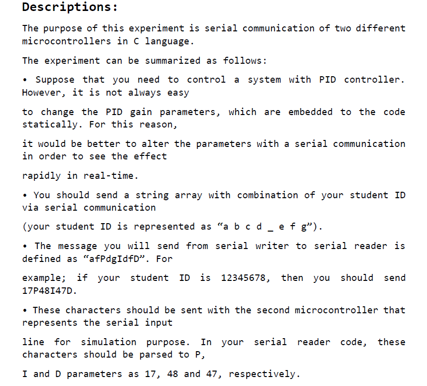
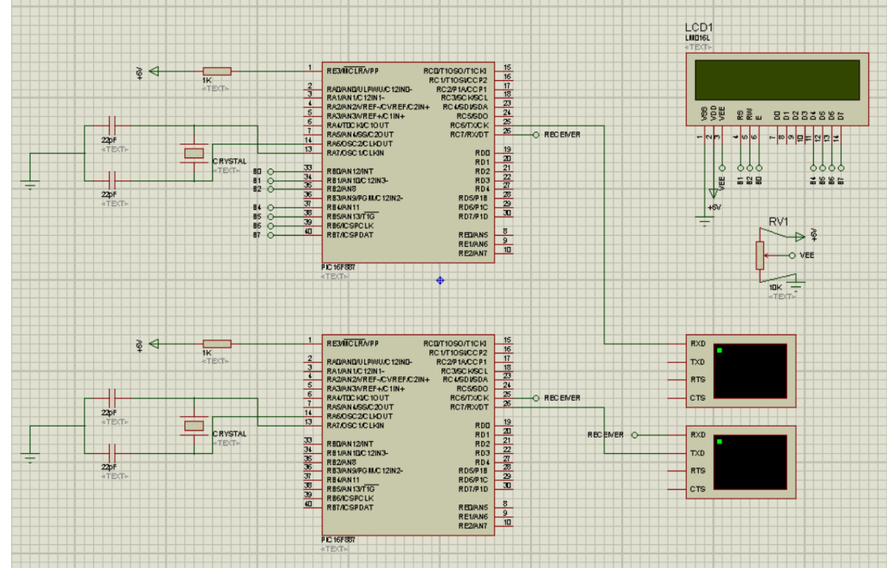
The purpose of this experiment is serial communication of two different microcontrollers in C language.
						The experiment can be summarized as follows: Suppose that you need to control a system with PID controller. However, it is not always easy
						to change the PID gain parameters, which are embedded to the code statically. For this reason,
						it would be better to alter the parameters with a serial communication in order to see the effect
						rapidly in real-time. You should send a string array with combination of your student ID via serial communication
						(your student ID is represented as “a b c d _ e f g”). The message you will send from serial writer to serial reader is defined as “afPdgIdfD”. For
						example; if your student ID is 12345678, then you should send 17P48I47D. These characters should be sent with the second microcontroller that represents the serial input
						line for simulation purpose. In your serial reader code, these characters should be parsed to P,
						I and D parameters as 17, 48 and 47, respectively. The purpose of this experiment is serial communication of two different microcontrollers in C language.
						The experiment can be summarized as follows: Suppose that you need to control a system with PID controller. However, it is not always easy
						to change the PID gain parameters, which are embedded to the code statically. For this reason,
						it would be better to alter the parameters with a serial communication in order to see the effect
						rapidly in real-time. You should send a string array with combination of your student ID via serial communication
						(your student ID is represented as “a b c d _ e f g”). The message you will send from serial writer to serial reader is defined as “afPdgIdfD”. For
						example; if your student ID is 12345678, then you should send 17P48I47D. These characters should be sent with the second microcontroller that represents the serial input
						line for simulation purpose. In your serial reader code, these characters should be parsed to P,
						I and D parameters as 17, 48 and 47, respectively.

Controlling A DC Motor (PWM)


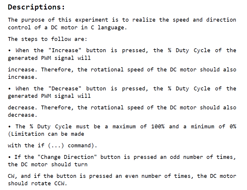
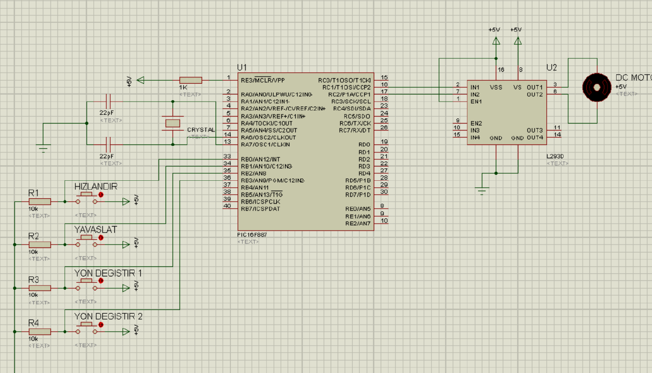
The purpose of this experiment is to realize the speed and direction control of a DC motor in C language.
						The steps to follow are: When the Increase button is pressed, the % Duty Cycle of the generated PWM signal will
						increase. Therefore, the rotational speed of the DC motor should also increase. When the Decrease button is pressed, the % Duty Cycle of the generated PWM signal will
						decrease. Therefore, the rotational speed of the DC motor should also decrease. The % Duty Cycle must be a maximum of 100% and a minimum of 0% (Limitation can be made
						with the if (...) command). If the Change Direction button is pressed an odd number of times, the DC motor should turn
						CW, and if the button is pressed an even number of times, the DC motor should rotate CCW. The purpose of this experiment is to realize the speed and direction control of a DC motor in C language.
						The steps to follow are: When the Increase button is pressed, the % Duty Cycle of the generated PWM signal will
						increase. Therefore, the rotational speed of the DC motor should also increase. When the Decrease button is pressed, the % Duty Cycle of the generated PWM signal will
						decrease. Therefore, the rotational speed of the DC motor should also decrease. The % Duty Cycle must be a maximum of 100% and a minimum of 0% (Limitation can be made
						with the if (...) command). If the Change Direction button is pressed an odd number of times, the DC motor should turn
						CW, and if the button is pressed an even number of times, the DC motor should rotate CCW.

Analog To Digital Converter (ADC)


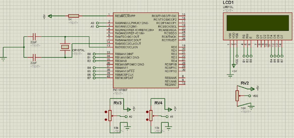
The purpose of this experiment is to implement an ADC process that occurs for each 2 seconds using a Timer in C language. ADC readings coming from 2 potentiometers should be made every 2 seconds by using a Timer and the first reading should be on the first line and the second reading should be on the second line of the LCD screen. The purpose of this experiment is to implement an ADC process that occurs for each 2 seconds using a Timer in C language. ADC readings coming from 2 potentiometers should be made every 2 seconds by using a Timer and the first reading should be on the first line and the second reading should be on the second line of the LCD screen.

Calculator With Microcontroller


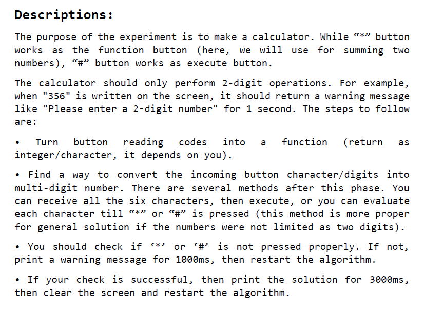
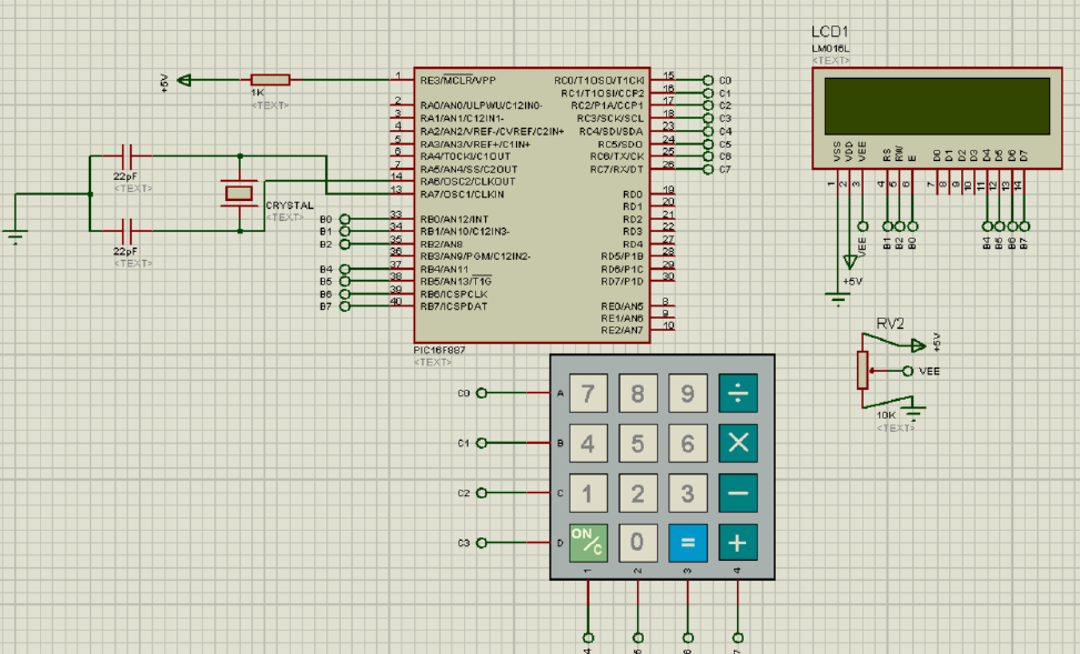
The purpose of the experiment is to make a calculator. While “*” button works as the function button (here, we will use for summing two numbers), “#” button works as execute button.
						The calculator should only perform 2-digit operations. For example, when 356 is written on the screen, it should return a warning message like Please enter a 2-digit number for 1 second. The steps to follow are: Turn button reading codes into a function (return as integer/character, it depends on you). Find a way to convert the incoming button character/digits into multi-digit number. There are several methods after this phase. You can receive all the six characters, then execute, or you can evaluate each character till “*” or “#” is pressed (this method is more proper for general solution if the numbers were not limited as two digits).You should check if * or # is not pressed properly. If not, print a warning message for 1000ms, then restart the algorithm. If your check is successful, then print the solution for 3000ms, then clear the screen and restart the algorithm. The purpose of the experiment is to make a calculator. While “*” button works as the function button (here, we will use for summing two numbers), “#” button works as execute button.
						The calculator should only perform 2-digit operations. For example, when 356 is written on the screen, it should return a warning message like Please enter a 2-digit number for 1 second. The steps to follow are: Turn button reading codes into a function (return as integer/character, it depends on you). Find a way to convert the incoming button character/digits into multi-digit number. There are several methods after this phase. You can receive all the six characters, then execute, or you can evaluate each character till “*” or “#” is pressed (this method is more proper for general solution if the numbers were not limited as two digits).You should check if * or # is not pressed properly. If not, print a warning message for 1000ms, then restart the algorithm. If your check is successful, then print the solution for 3000ms, then clear the screen and restart the algorithm.

TMR0 Interrupt Application


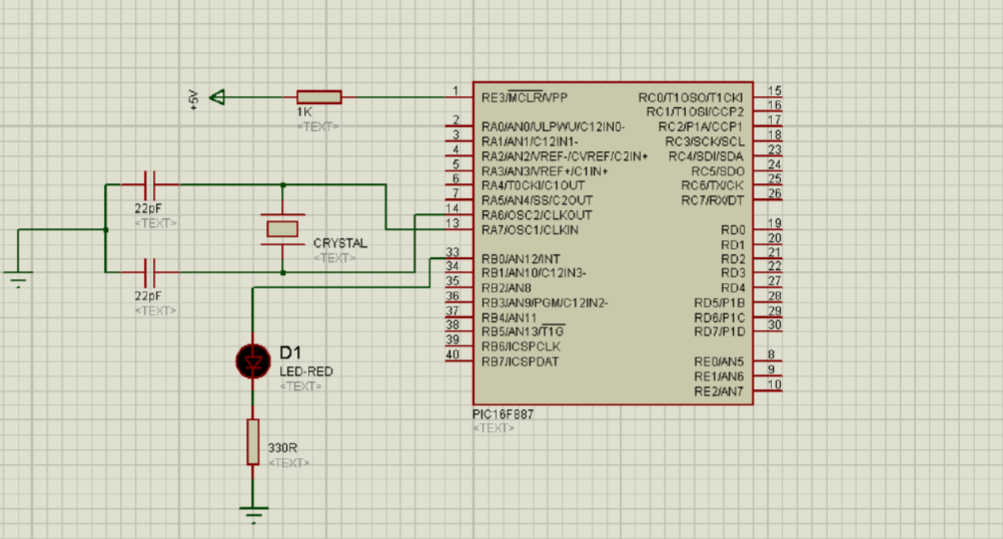
The purpose of the experiment is to demonstrate the use of the interrupt and timer with assembly instructions. In the experiment, using the TMRO interrupt, the LED connected to the B0 pin is requested to blink at 1-second intervals. The purpose of the experiment is to demonstrate the use of the interrupt and timer with assembly instructions. In the experiment, using the TMRO interrupt, the LED connected to the B0 pin is requested to blink at 1-second intervals.

Delay With Assembly


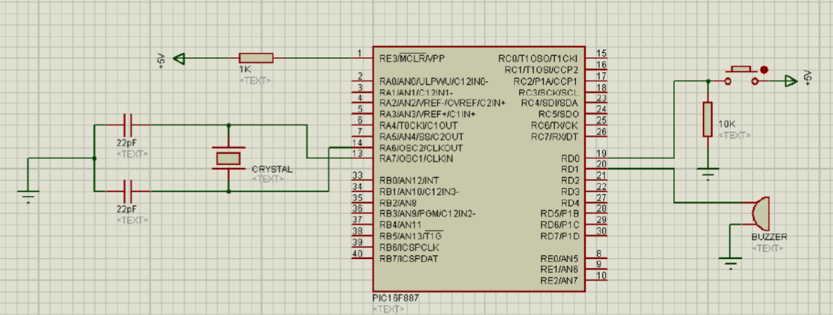
The purpose of the experiment is to create delay loops with assembly instructions. In the experiment, when a button connected to the DO pin is pressed, the buzzer connected to the D1 pin is requested to turn on and off at 3 second intervals. The purpose of the experiment is to create delay loops with assembly instructions. In the experiment, when a button connected to the DO pin is pressed, the buzzer connected to the D1 pin is requested to turn on and off at 3 second intervals.

Assembly Application


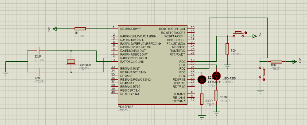
The purpose of this experiment is to define the input and output pins in assembly language and accordingly, to perform the LED on application with the button. In the experiment, when the buttons connected to the DO and D2 pins are pressed, the LED connected to the D1 and D3 pins should turn on, otherwise it should turn off. Note that the buttons are connected in different configurations. The purpose of this experiment is to define the input and output pins in assembly language and accordingly, to perform the LED on application with the button. In the experiment, when the buttons connected to the DO and D2 pins are pressed, the LED connected to the D1 and D3 pins should turn on, otherwise it should turn off. Note that the buttons are connected in different configurations.